Cleanroom Design in 10 Easy Steps
"Easy" may not be a word that comes to mind for designing such sensitive environments. However, that doesn't mean you can't produce a solid cleanroom design by tackling issues in a logical sequence. This article covers each key step, down to handy application-specific tips for adjusting load calculations, planning exfiltration paths, and angling for adequate mechanical room space relative to the cleanroom's class.
Many manufacturing processes need the very stringent environmental conditions provided by a cleanroom. Because cleanrooms have complex mechanical systems and high construction, operating, and energy costs, it is important to perform the cleanroom design in a methodical way. This article will present a step-by-step method for evaluating and designing cleanrooms, factoring in people/material flow, space cleanliness classification, space pressurization, space supply airflow, space air exfiltration, space air balance, variables to be evaluated, mechanical system selection, heating/cooling load calculations, and support space requirements.
Step One: Evaluate Layout for People/Material Flow
It is important to evaluate the people and material flow within the cleanroom suite. Cleanroom workers are a cleanroom's largest contamination source and all critical processes should be isolated from personnel access doors and pathways.
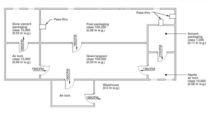
The most critical spaces should have a single access to prevent the space from being a pathway to other, less critical spaces. Some pharmaceutical and biopharmaceutical processes are susceptible to cross-contamination from other pharmaceutical and biopharmaceutical processes. Process cross-contamination needs to be carefully evaluated for raw material inflow routes and containment, material process isolation, and finished product outflow routes and containment. Figure 1 is an example of a bone cement facility that has both critical process ("Solvent Packaging", "Bone Cement Packaging") spaces with a single access and air locks as buffers to high personnel traffic areas ("Gown", "Ungown").
Step Two: Determine Space Cleanliness Classification

To be able to select a cleanroom classification, it is important to know the primary cleanroom classification standard and what the particulate performance requirements are for each cleanliness classification. The Institute of Environmental Science and Technology (IEST) Standard 14644-1 provides the different cleanliness classifications (1, 10, 100, 1,000, 10,000, and 100,000) and the allowable number of particles at different particle sizes.
For example, a Class 100 cleanroom is allowed a maximum of 3,500 particles/cu ft and 0.1 microns and larger, 100 particles/cubic ft. at 0.5 microns and larger, and 24 particles/cubic ft. at 1.0 microns and larger. This table provides the allowable airborne particle density per cleanliness classification table:
| ISO 14644-1 Cleanroom Standards | |||||||
|---|---|---|---|---|---|---|---|
| Classification | Maximum Particles/m3 | FED STD 209E Equivalent | |||||
| ≥0.1µm | ≥0.2µm | ≥0.3µm | ≥0.5µm | ≥1µm | ≥5µm | ||
| ISO 1 | 10 | 2.37 | 1.02 | 0.35 | 0.083 | 0.0029 | |
| ISO 2 | 100 | 23.7 | 10.2 | 3.5 | 0.83 | 0.029 | |
| ISO 3 | 1,000 | 237 | 102 | 35 | 8.3 | 0.029 | Class 1 |
| ISO 4 | 10,000 | 2,370 | 1,020 | 352 | 83 | 2.9 | Class 10 |
| ISO 5 | 100,000 | 23,700 | 10,200 | 3,520 | 832 | 29 | Class 100 |
| ISO 6 | 1.0 x 10⁶ | 237,000 | 102,000 | 35,200 | 8,320 | 293 | Class 1,000 |
| ISO 7 | 1.0 x 10⁷ | 2.37 x 10⁶ | 1,020,000 | 352,000 | 83,200 | 2,930 | Class 10,000 |
| ISO 8 | 1.0 x 10⁸ | 2.37 x 10⁷ | 1.02 x 10⁷ | 3,520,000 | 832,000 | 29,300 | Class 100,000 |
| ISO 9 | 1.0 x 10⁹ | 2.37 x 10⁸ | 1.02 x 10⁸ | 35,200,000 | 8,320,000 | 293,000 | Room Air |
Space cleanliness classification has a substantial impact on a cleanroom's construction, maintenance, and energy cost. It is important to carefully evaluate reject/contamination rates at different cleanliness classifications and regulatory agency requirements, such as the Food and Drug Administration (FDA). Typically, the more sensitive the process, the more stringent cleanliness classification should be used. This table provides cleanliness classifications for a variety of manufacturing processes:
| Industrial Applications | |
|---|---|
| Application | Classification |
| Aerospace | ISO Class 5-7 |
| Assembly of Touch Screen Membranes | ISO Class 7 |
| Composite Materials | ISO Class 8 |
| General Industrial | ISO Class 8 |
| Isolation of Injection Molded Parts | ISO Class 7-8 |
| Optical | ISO Class 5-7 |
| Electronics | |
| Application | Classification |
| Semiconductor | ISO Class 5 |
| SMT Assembly | ISO Class 7-8 |
| Solar | ISO Class 5-7 |
| Wafer Board | ISO Class 5 |
| Consumables and Pharmaceuticals | |
| Application | Classification |
| E-Liquid | ISO Class 7-8 |
| Food Packaging | No Classification |
| Nutraceutical Packaging | ISO Class 7-8 |
| Pharmaceutical Compounding | ISO Class 7 |
| Pharmaceutical Packaging | ISO Class 8 |
| Sterile Compounding | ISO Class 5 |
| Medical Devices | |
| Application | Classification |
| Device Reprocessing | ISO Class 7 |
| Inplantable Devices | ISO Class 5 |
| Medical Device Packaging | ISO Class 7-8 |
Your manufacturing process may need a more stringent cleanliness class depending upon its unique requirements. Be careful when assigning cleanliness classifications to each space; there should be no more than two orders of magnitude difference in cleanliness classification between connecting spaces. For example, it is not acceptable for a Class 100,000 cleanroom to open into a Class 100 cleanroom, but it is acceptable for a Class 100,000 cleanroom to open into a Class 1,000 cleanroom.
Looking at our bone cement packaging facility (Figure 1), "Gown", Ungown" and "Final Packaging" are less critical spaces and have a Class 100,000 (ISO 8) cleanliness classification, "Bone Cement Airlock" and "Sterile Airlock" open to critical spaces and have Class 10,000 (ISO 7) cleanliness classification; 'Bone Cement Packaging" is a dusty critical process and has Class 10,000 (ISO 7) cleanliness classification, and 'Solvent Packaging" is a very critical process and is performed in Class 100 (ISO 5) laminar flowhoods in a Class 1,000 (ISO 6) cleanroom.
Step Three: Determine Space Pressurization
Maintaining a positive air space pressure, in relation to adjoining dirtier cleanliness classification spaces, is essential in preventing contaminants from infiltrating into a cleanroom. It is very difficult to consistently maintain a space's cleanliness classification when it has neutral or negative space pressurization. What should the space pressure differential be between spaces? Various studies evaluated contaminant infiltration into a cleanroom vs. space pressure differential between the cleanroom and adjoining uncontrolled environment. These studies found a pressure differential of 0.03 to 0.05 in w.g. to be effective in reducing contaminant infiltration. Space pressure differentials above 0.05 in. w.g. do not provide substantially better contaminant infiltration control then 0.05 in. w.g.
Keep in mind, a higher space pressure differential has a higher energy cost and is more difficult to control. Also, a higher pressure differential requires more force in opening and closing doors. The recommended maximum pressure differential across a door is 0.1 in. w.g. at 0.1 in. w.g., a 3 foot by 7 foot door requires 11 pounds of force to open and close. A cleanroom suite may need to be reconfigured to keep the static pressure differential across doors within acceptable limits.
Our bone cement packaging facility is being built within an existing warehouse, which has a neutral space pressure (0.0 in. w.g.). The air lock between the warehouse and "Gown/Ungown" does not have a space cleanliness classification and will not have a designated space pressurization. "Gown/Ungown" will have a space pressurization of 0.03 in. w.g. "Bone Cement Air Lock" and "Sterile Air Lock" will have a space pressurization of 0.06 in. w.g. "Final Packaging" will have a space pressurization of 0.06 in. w.g. "Bone Cement Packaging" will have a space pressurization of 0.03 in. w.g., and a lower space pressure than 'Bone Cement Air Lock" and "Final Packaging" in order to contain the dust generated during packaging.
The air filtering into the 'Bone Cement Packaging" is coming from a space with the same cleanliness classification. Air infiltration should not go from a dirtier cleanliness classification space to a cleaner cleanliness classification space. "Solvent Packaging" will have a space pressurization of 0.11 in. w.g. Note, the space pressure differential between the less critical spaces is 0.03 in. w.g. and the space differential between the very critical "Solvent Packaging" and "Sterile Air Lock" is 0.05 in. w.g. The 0.11 in. w.g. space pressure will not require special structural reinforcements for walls or ceilings. Space pressures above 0.5 in. w.g. should be evaluated for potentially needing additional structural reinforcement.
Step Four: Determine Space Supply Airflow
The space cleanliness classification is the primary variable in determining a cleanroom's supply airflow. Looking at table 3, each clean classification has an air change rate. For example, a Class 100,000 cleanroom has a 15 to 30 ach range. The cleanroom's air change rate should take the anticipated activity within the cleanroom into account. A Class 100,000 (ISO 8) cleanroom having a low occupancy rate, low particle generating process, and positive space pressurization in relation to adjacent dirtier cleanliness spaces might use 15 ach, while the same cleanroom having high occupancy, frequent in/out traffic, high particle generating process, or neutral space pressurization will probably need 30 ach.
The designer needs to evaluate his specific application and determine the air change rate to be used. Other variables affecting space supply airflow are process exhaust airflows, air infiltrating in through doors/openings, and air exfiltrating out through doors/openings. IEST has published recommended air change rates in Standard 14644-4.
Looking at Figure 1, "Gown/Ungown" had the most in/out travel but is not a process critical space, resulting in 20 a ch., 'Sterile Air Lock" and "Bone Cement Packaging Air Lock" are adjacent to critical production spaces and in the case of the "Bone Cement Packaging Air Lock", the air flows from the air lock into the packaging space. Though these air locks have limited in/out travel and no particulate generating processes, their critical importance as a buffer between "Gown/Ungown" and manufacturing processes results in their having 40 ach.
"Final Packaging" places the bone cement/solvent bags into a secondary package which is not critical and results in a 20 ach rate. "Bone Cement Packaging" is a critical process and has a 40 ach rate. 'Solvent Packaging" is a very critical process which performed in Class 100 (ISO 5) laminar flow hoods within a Class 1,000 (ISO 6) cleanroom. 'Solvent Packaging" has very limited in/out travel and low process particulate generation, resulting in a 150 ach rate.
Cleanroom Classification and Air Changes Per Hour
Air cleanliness is achieved by passing the air through HEPA filters. The more often the air passes through the HEPA filters, the fewer particles are left in the room air. The volume of air filtered in one hour divided by the volume of the room gives the number of air changes per hour.
| Required air changes per hour (ACH) | |
|---|---|
| ISO Class | Average number of air changes per hour |
| ISO 5 | 240–360 air changes per hour (unidirectional airflow) |
| ISO 6 | 90–180 air changes per hour |
| ISO 7 | 30–60 air changes per hour |
| ISO 8 | 10–25 air changes per hour |
| Conventional building | 2–4 air changes per hour |
The above-suggested air changes per hour are only a design rule of thumb. They should be computed by an HVAC cleanroom expert, as many aspects must be taken into consideration, such as the size of the room, the number of people in the room, the equipment in the room, the processes involved, the heat gain, etc.
Step Five: Determine Space Air Exfiltration Flow
The majority of cleanrooms are under positive pressure, resulting in planned air exfiltrating into adjoining spaces having lower static pressure and unplanned air exfiltration through electrical outlets, light fixtures, window frames, door frames, wall/floor interface, wall/ceiling interface, and access doors. It is important to understand rooms are not hermetically sealed and do have leakage. A well-sealed cleanroom will have a 1% to 2% volume leakage rate. Is this leakage bad? Not necessarily.
First, it is impossible to have zero leakage. Second, if using active supply, return, and exhaust air control devices, there needs to be a minimum of 10% difference between supply and return airflow to statically decouple the supply, return, and exhaust air valves from each other. The amount of air exfiltrating through doors is dependent upon the door size, the pressure differential across the door, and how well the door is sealed (gaskets, door drops, closure).
We know the planned infiltration/exfiltration air goes from one space to the other space. Where does the unplanned exfiltration go? The air relieves within the stud space and out the top. Looking at our example project (Figure 1), the air exfiltration through the 3- by 7- foot door is 190 cfm with a differential static pressure of 0.03 in w.g. and 270 cfm with a differential static pressure of 0.05 in. w.g.
Step Six: Determine Space Air Balance
Space air balance consists of adding all the airflow into the space (supply, infiltration) and all the airflow leaving the space (exhaust, exfiltration, return) being equal. Looking at the bone cement facility space air balance (Figure 2), "Solvent Packaging" has 2,250 cfm supply airflow and 270 cfm of air exfiltration to the 'Sterile Air Lock", resulting in a return airflow of 1,980 cfm. "Sterile Air Lock" has 290 cfm of supply air, 270 cfm of infiltration from 'Solvent Packaging", and 190 cfm exfiltration to "Gown/Ungown", resulting in a return airflow of 370 cfm.
"Bone Cement Packaging" has 600 cfm supply airflow, 190 cfm of air filtration from 'Bone Cement Air Lock", 300 cfm dust collection exhaust, and 490 cfm of return air. "Bone Cement Air Lock" has 380 cfm supply air, 190 cfm exfiltration to 'Bone Cement Packaging" has 670 cfm supply air, 190 cfm exfiltration to "Gown/Ungown". "Final Packaging" has 670 cfm supply air, 190 cfm exfiltration to 'Gown/Ungown", and 480 cfm of return air. "Gown/Ungown" has 480 cfm of supply air, 570 cfm of infiltration, 190 cfm of exfiltration, and 860 cfm of return air.
We have now determined the cleanroom supply, infiltration, exfiltration, exhaust, and return airflows. The final space return airflow will be adjusted during start-up for unplanned air exfiltration.
Step Seven: Assess Remaining Variables
Other variables needing to be evaluated include:
- Temperature: Cleanroom workers wear smocks or full bunny suits over their regular clothes to reduce particulate generation and potential contamination. Because of their extra clothing, it is important to maintain a lower space temperature for worker comfort. A space temperature range between 66°F and 70° will provide comfortable conditions.
- Humidity: Due to a cleanroom's high airflow, a large electrostatic charge is developed. When the ceiling and walls have a high electrostatic charge and space has a low relative humidity, airborne particulate will attach itself to the surface. When the space relative humidity increases, the electrostatic charge is discharged and all the captured particulate is released in a short time period, causing the cleanroom to go out of specification. Having high electrostatic charge can also damage electrostatic discharge sensitive materials. It is important to keep the space relative humidity high enough to reduce the electrostatic charge build-up. An RH or 45% +5% is considered the optimal humidity level.
- Laminarity: Very critical processes might require laminar flow to reduce the chance of contaminates getting into the air stream between the HEPA filter and the process. IEST Standard #IEST-WG-CC006 provides airflow laminarity requirements.
- Electrostatic Discharge: Beyond the space humidification, some processes are very sensitive to electrostatic discharge damage and it is necessary to install grounded conductive flooring.
- Noise Levels and Vibration: Some precision processes are very sensitive to noise and vibration.
Step Eight: Determine Mechanical System Layout
A number of variables affect a cleanroom's mechanical system layout: space availability, available funding, process requirements, cleanliness classification, required reliability, energy cost, building codes, and local climate. Unlike normal A/C systems, cleanroom A/C systems have substantially more supply air than needed to meet cooling and heating loads.
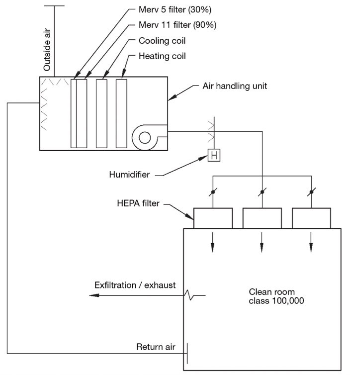
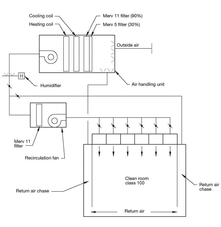
Class 100,000 (ISO 8) and lower ach Class 10,000 (ISO 7) cleanrooms can have all the air go through the AHU. Looking at Figure 3, the return air and outside air are mixed, filtered, cooled, reheated, and humidified before being supplied to terminal HEPA filters in the ceiling. To prevent contaminant recirculation in the cleanroom, the return air is picked up by low wall returns. For higher class 10,000 (ISO 7) and cleaner cleanrooms, the airflows are too high for all the air to go through the AHU. Looking at Figure 4, a small portion of the return air is sent back to the AHU for conditioning. The remaining air is returned to the circulation fan.
Alternatives to Traditional Air Handling Units
Fan filter units, also known as integrated blower modules, are a modular cleanroom filtration solution with some advantages over traditional air handling systems. They are applied in both small and large spaces with a cleanliness rating as low as ISO Class 3. Air change rates and cleanliness requirements determine the number of fan filters required. An ISO Class 8 cleanroom ceiling may only require 5-15% of ceiling coverage while an ISO Class 3 or cleaner cleanroom may require 60-100% coverage.
Step Nine: Perform Heating/Cooling Calculations
When performing the cleanroom heating/cooling calculations, take the following into consideration:
- Use the most conservative climate conditions (99.6% heating design, 0.4% drybulb/median wetbulb cooling deign, and 0.4% wetbulb/median drybulb cooling design data).
- Include filtration into calculations.
- Include humidifier manifold heat into calculations.
- Include process load into calculations.
- Include recirculation fan heat into calculations.
Step Ten: Fight for Mechanical Room Space
Cleanrooms are mechanically and electrically intensive. As the cleanroom's cleanliness classification becomes cleaner, more mechanical infrastructure space is needed to provide adequate support to the cleanroom. Using a 1,000-sq-ft cleanroom as an example, a Class 100,000 (ISO 8) cleanroom will need 250 to 400 sq ft of support space, a Class 10,000 (ISO 7) cleanroom will need 250 to 750 sq ft of support space, a Class 1,000 (ISO 6) cleanroom will need 500 to 1,000 sq ft of support space, and a Class 100 (ISO 5) cleanroom will need 750 to 1,500 sq ft of support space.
The actual support square footage will vary depending upon the AHU airflow and complexity (Simple: filter, heating coil, cooling coil, and fan; Complex: sound attenuator, return fan, relief air section, outside air intake, filter section, heating section, cooling section, humidifier, supply fan, and discharge plenum) and number of dedicated cleanroom support systems (exhaust, recirculation air units, chilled water, hot water, steam, and DI/RO water). It is important to communicate the required mechanical equipment space square footage to the project architect early in the design process.
Final Thoughts
Cleanrooms are like race cars. When properly designed and built, they are highly efficient performance machines. When poorly designed and built, they operate poorly and are unreliable. Cleanrooms have many potential pitfalls, and supervision by an engineer with extensive cleanroom experience is recommended for your first couple of cleanroom projects.
©Vincent A. Sakraida, 2008. Reprinted with permission from Engineered System. Original issue date March 31st, 2008, www.esmagazine.com.
- More Information
- Related Products
-
-

Cleanroom Design
Our experts can help you design and build your cleanroom. -

Meters & Testing
Particle counter and anemometers for cleanroom testing. -

Cleanroom Furniture
Tables, furniture and storage for your cleanroom environment. -

Gowning Furniture
Gowning benches, garment racks, dispensers and more. -

Consumable Supplies
Consumable garments and safety products for your environment. -
Cleanroom Apparel
Smocks, frocks, lab coats, coveralls, intersuits and more. -

Cleanroom Cleaning
Mops, vacuums and waste management for your cleanroom.
-
Sign up to be the first to know about new products, promotions and industry news.
Sign UpProduction Automation Corporation is ISO 9001:2015 Certified.